Have you ever used targets and total stations from different manufacturers (e.g. using a Leica Target with a Trimble instrument) and wondered why you’re having systematic errors in your data? Chances are you need to correct your constants.
One of the most common causes of error in surveys seems to be caused by the lack of understanding of prism constants. In today’s age of Land Surveying, the most commonly used targets contain a prism reflector that is used to return the signal back to the EDM of the Total Station. These prisms often have different characteristics defined by their construction which differs between manufacturers. In this article, I will try to explain:
- what a prism constant is and how it affects your EDM measurements
- how most manufacturers define their prism constants
- a list and comparison of the most commonly used prism and their constants and how to correctly use prism constants with instruments from other manufacturers (e.g. how to use a Leica prism constant with Trimble).
With so many manufacturers out there, this article would become too long and difficult to follow. Therefore I will be focusing on the most common equipment used throughout the world.
This article will focus only on Corner-cube prisms (reflectors). The flat reflective targets have no constant as the signal bounces directly off the target’s surface.
What are prism constants
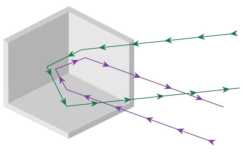
To define what the prism constant is, we must first explain how a prism target works. In principle, the target reflector is a piece of glass that bounces off the signal in the same direction it came from. The image below shows how the incoming EDM signal is reflected in the same direction it came from.

As you can see, regardless of the point of entry of the signal, it will be reflected in the same direction where it came from. Without going into much detail, this type of reflector is the most commonly used due to the simplicity of the design.
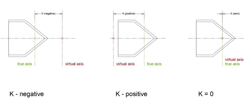
How does a target constant come into play? Well, the constant is defined as the correction of the measured distance based on the physical and design characteristics of the prism or reflector in the instrument. This is calculated based on the type and length of the glass prism itself and the mechanical mounting of the prism on the target holder. To put this into perspective, the sketch below shows a 2D view of a prism. The magnitude of the prism constant is defined as the distance between the true axis of the prism holder (the point around which the prism tilts up and down) and the virtual axis (the theoretical turning point S0).

True Axis represents the vertical axis of the target (i.e. centered on the point). Most commercially available prisms will always have the virtual axis behind the true axis, making the measured distance too long, thus requiring a negative correction for the distance (K is negative). Best case scenario is when virtual axis and true axis coincide, requiring no correction. In this case, there is a minimal effect on measurements of angles and distances caused by inaccurate prism alignment.
Prism constant vs prism offset
Although these terms are commonly interchanged, they technically refer to different values. Prism constant is often referred to as prism offset, however this might not always be the correct definition.
If you are referring to the prism glass, the constant can be referred to as the offset. However, when the context is the surveying prism (including the body of the holder), the prism offset is actually the height difference between the mounting point of the survey prism (survey target) and the centre of the prism glass. In this case, the prism offset is a vertical offset, rather than a horizontal one.
To avoid confusion, whenever discussing surveying prisms on this site, the prism constant is the value added to the EDM path, where as prism offset is the height of the prism.
How manufacturers define their prism constants?
Most big-name manufacturers (Trimble, Topcon, Sokkia, Pentax, and Nikon) will define all prism constants based on their physical characteristics mentioned above, making them absolute offsets. The only exception is Leica which defines the prism constant with reference to its standard round prism (GPH1 + GRP1). The absolute correction for this prism is -34.4mm, which Leica defines as a constant 0.0mm. It is essential to keep in mind that if non-Leica prisms are used with Leica instruments, the constant of the prism needs to be converted. Similarly, when a Leica prism is used with a non-Leica instrument, the same process applies, but in reverse.
Example – using a non-Leica prism with a Leica instrument
Consider we have a non-Leica prism with a manufacturer defined constant (absolute offset) of -17mm. In this case we use the following formula to compute the correction required in the Leica instrument:
Leica Offset (Kl) = Absolute Offset (K) + 34.4 mm
Replacing the value in the formula above will get us a value of +17.4mm, an adjustment that must be made on the Leica Instrument.
Leica Offset (Kl) = -17 + 34.4 = +17.4mm
Example – using a Leica prism with a non Leica instrument
In this case the process is similar, but in reverse. We need to subtract -34.4mm from the Leica defined offset (Kl):
Absolute Offset (K) = Leica Offset (Kl) – 34.4 mm
Considering a Leica prism with the manufacturer defined constant (Kl) of 0.0mm, we can compute the required value that needs to be used in the non-Leica instrument:
Absolute Offset (K) = 0.0 – 34.4 = -34.4mm
In practice, it is very common for surveyors to use prisms from different manufacturers and use the constants written on the body of the prism. Or, alternatively, switching from a Leica instrument to a non-Leica instrument, but not knowing the difference in prism constant definitions. This causes a large number of issues with topographical surveys, especially when creating control networks.
Most common commercially available prisms and their constants
The table below serves as a reference and contains the most common prisms used in the industry and their constants in the Absolute and Leica systems.
| Prism Name | Leica constant (Kl) | Non-Leica (Trimble, Topcon, Sokkia, Pentax, and Nikon) constant (K) |
| Leica 360° Mini GRZ101 | +30.0mm | -4.4mm |
| Leica 360° Prism – GRZ4, GRZ122 | +23.1mm | -11.3mm |
| Leica Mini GMP111 | +17.5mm | -16.9mm |
| Leica Standard Prism GPH1, GPR121, GPR111 | 0mm | -34.4mm |
| Prism from Nikon, Topcon, Spectra Precision | +34.4mm | 0mm |
| Prisms from Sokkia, Pentax, Topcon | +4.4mm | -30.0mm |
| Reflecting Foil / Reflective Flat Targets | +34.4mm | 0mm |
| Trimble 360 Prism | +36.4mm | +2.0mm |
| Trimble Active Track 360 Target | +56.4mm | +22.0mm |
| Trimble Mini 360 Prism | +36.4mm | +2.0mm |
| Trimble MultiTrack Target | +44.4mm | +10.0mm |
| Trimble Prism Ring for RMT604/606 | +36.4mm | +2.0mm |
| Trimble R10 360 Prism | +36.4mm | +2.0mm |
| Trimble Robotic Target Kit with Target ID | +36.4mm | +2.0mm |
| Trimble Traverse Prism (similar to Zeiss ETR, KTR, KTO, KTM) | -0.6mm | -35.0mm |
| Trimble VX&S Series 360 Prism | +36.4mm | +2.0mm |
| Trimble Mini Prism | +16.4mm | -18.0mm |
| Trimble Large Monitoring Prism (62mm) | -5.6mm | -40.0mm |
| Trimble Small Monitoring Prism (25mm) | +17.4mm | -17.0mm |
This list isn’t exhaustive, but hopefully it can serve as a guide when switching instruments or mixing target manufacturers.
What prism constant do I use?
As presented above, different manufacturers define prism constants in their own way. These can be broken down to two different groups:
- Leica
- Other manufacturers (Trimble, Sokkia, Topcon etc)
You should always use the prism constant as defined by the manufacturer of your instrument. The choice of what prism constant you need depends on both the instrument (total station) manufacturer, as well as the prism manufacturer.
If you’re unsure what prism constant you should use, use the flow diagram below to decide.
To see more surveying prisms and find out their characteristics such as prism constant, prism offset or mount type, please go to the dedicated page about survey prisms and targets.


Complicating things further, I discovered that even within a brand, the sign of the constant may not be consistent. In 2022 our college acquired Trimble C3 total stations (Nikons under the hood) and controllers with Trimble Access 2022 software. If you enter the prism constant directly into the total station, the sign convention is opposite the common convention. That is, you enter +30 mm to correct measured 50.000 m to true 49.970 m. However if the instrument setting is left at 0 and the constant is instead entered in Access on the controller, then you enter -30 mm to correct measured 50.000 m to true 49.970 m. I suppose this may change in the future to resolve the inconsistency. Always check the whole system (instrument, prism, controller) and re-check after any changes!
Dan, thank you for your valuable input.
You are completely right. Often there are inconsistencies with the same manufacturers as well. Sometimes these differences are not documented anywhere and it creates hours if not days of head scratching, trying to figure out the cause of errors.
And I agree, it shouldn’t be just a case of checking the prism constant, but having multiple redundant checks with every change in the system.
Hi. I noticed one strange thing when I once tried to use Topcon ADS11 prism with Leica total station. Absolute constant is 0 mm. With that value I got correctly measured distances. The problem is that by tilting the prism, measured height difference changes. Any thought on that? It is like the physical center of the prism sticks 3 cm from the true axis, so any change in the tilt affects the measured height difference. Quite strange. What is the point of having such a prism? Or, I was doing something wrong… Anyway, nice and informative text 🙂
Nick,
Thank you for your feedback.
I believe the prism you mentioned (Topcon ADS11) is a dual-constant prism (-30mm or 0mm) absolute constant. Which means with a Leica instrument it should be +4.4mm (if in a -30mm configuration). Could you try slightly tweaking the constant and see if that reduces your height error?
What kind of height differences do you get? Can you give me an example of an observation (Instrument Height, Slope Distance, Vertical Angle, Target Height and Height error). Do you have more than one prism of this type you can check against? I do not have one of these prisms on hand to double check.
Manufacturers have different reasons to these offsets. If I’m not mistaken, some use the offset to actually minimise angular errors when instrument and prism aren’t perfectly aligned. Although I’m unsure how that works out.
Hi Florentin
I think your 3 pics showing 3 different prism types are not correct.
They are (I think) for Leica but are not true position and confuse
issue. Leica came out with a white paper describing how their
prism offset/constants work and have confused many.
The third pic where virtual and true coincide, is for leica -34.4mm
standard prism.
Due to refractive index of glass , a standard prism needs to sit
circa 20mm (from apex of glass) to plumb/true point. This is true
for all instruments, but causes misalignments in angles. Topcon
etc shift prism apex 20mm+/- in front of plumb point to get 0 constant(PC)
in setup. Don’t need to change the PC when in direct/reflectorless etc.
Leica have ‘hard set’ their instruments to measure -34.4mm short in
standard mode. When you choose to use reflectorless with leica,
the instrument applies +34.4mm to the measurement so it’s correct.
I don’t use leica. Use Trimble and you select prism and Trimble
selects correct constant, but the instrument, when pointed at wall in DR
selects 0mm constant, i.e it is set up to measure correct distance
unlike leica instr.
Leica have set their instruments at -34.4mm as starting point and work back
from here for smaller prisms etc so it’s a little bit swiss…
Need to be careful if using non leica prism with leica instr.
(not advised).
Hope this helps
Hi Kieran,
Thank you for your feedback. The 3 prism types are for the actual prism construction (not Leica). As detailed in the article, Leica is the only manufacturer that hard-coded the -34.4mm constant in their instruments. So all their constants are not true values, but rather with this -34.4mm constant offset applied. Like you have mentioned, it is confusing especially when mixing Leica Targets with non-Leica instruments (Trimble, Topcon etc) or vice-versa, as most targets will have the constant (as defined by the manufacturer) printed on them.
– Florentin
Hi Florentin
"The magnitude of the prism constant is defined as the distance between the true axis of the prism holder (the point around which the prism tilts up and down) and the virtual axis (the theoretical turning point S0)."
I am fairly certain this is not correct.
I could discuss offline if you wish. Virtual and theoretical are different.
Saying when virtual and true coincide there is no correction is off the mark.
(this is leica situation and correction is -34.4mm.
Great website and resource.
Well done
Kieran
Thank you for the reply, Kieran. I believe we are saying the same thing but from a different perspective and different wording. Like you, I am a predominantly Trimble user. And the sketches were done from the perspective of a non-Leica instrument. The constants are the absolute values (not the Leica offsets), hence why I mentioned virtual and true axis coincidence. Probably would have been better to present the virtual axis with the nodal point of the prism?
But you are right, it’s not applicable to Leica prisms as it wasn’t intended to be. Feel free to get in touch by email contact@geomatics.cc with your suggestions on how to improve the information in the article.
HI Florentin
Not sure on email so pop it in here.
Appreciate if you don’t put this up.
I have ‘researched this 3-4 years on/off
and still have queries. Tricky one, hence
many people get tripped up including myself.
Feel free to email me.
p.s.
If you email me I will send on sketch .
regards
kieran
[…] details: point names for setup, backsight and foresight(s), instrument & target heights & prism constants, instrument used, residuals […]
So much confusion and uncertainty… can only imagine how incorrect measurements are had.
The sketch for K = positive is an impossibility. The true axis cannot be in front of the nodal point of the prism and K be positive. The entirety of the prism must be in front of the true axis in order for K to be positive.
Hi Steve,
Thank you for your input. The sketch was done as as exaggeration of the scenarios, but I agree it is misleading as the nodal point would have to fall inside the prism body. I will update this soon to reflect yours and other reader’s feedback.
– Florentin