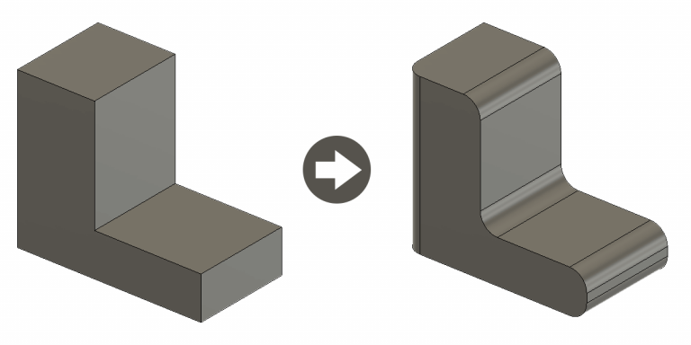
In this article I will explain the fillet tool in AutoCAD & how to fillet 2D and 3D elements.
What is a fillet?
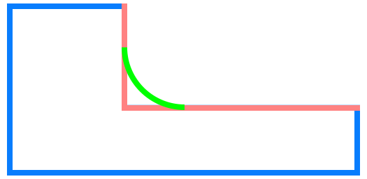
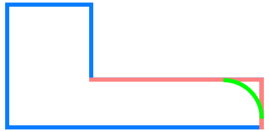
A filet is term used in many industries and can be defined in different ways, but it simple terms it is a rounded sharp edge or corner. In AutoCAD you’ll often often see the word round used, but the word is synonymous with fillet. The general consensus within AutoCAD is that an inside corner is called a fillet and an outside corner is called a round.
Fillet vs other design element
Very often fillets are easily confused with other design features such as chamfers and bevels. Whilst the these features design elements have a common purpose, they aren’t interchangeable and typically have a different use-case.
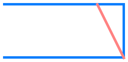

Fillet – A fillet or round connects two objects with a tangent arc in 2D, or creates a rounded transition between the adjacent faces of a 3D solid.
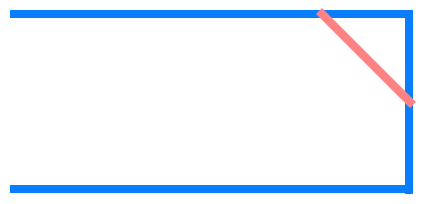
Chamfer – A chamfer connects two objects with an angled line in 2D, or creates an angled face between the adjacent faces of a 3D solid.
Bevel – Similar to a chamfer, a bevel connects two objects with and angled line in 2D or creates an angled face between adjacent faces of a solid in 3D.
As you can see, chamfers and bevels are pretty much the same thing, at least from AutoCAD’s perspective. However, there is a slight difference which defines which term is appropriate for use. The difference is: a chamfer is typically a 45° angle added to the edge of a feature, while a bevel is a slope from a horizontal or vertical edge.
Types of fillet
Fillets can be classified in a few different categories, depending on a several factors. On a day to day basis you will encounter the following types of fillets in AutoCAD:
Fillet based on profile
Depending on the cross profile of the fillet, these can be categorised into:
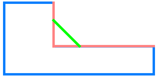
- mitre (which is for all intents and purposes a chamfer)
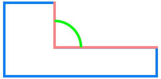
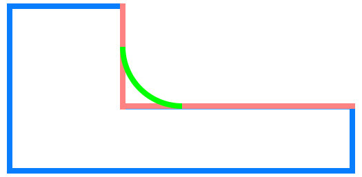
- convex (the profile creates a convex shape)
- concave (the profile creates a concave shape)
Fillet based on object type
If you categorise fillets based on the objects they are applied to, then these can be split into the following two categories:
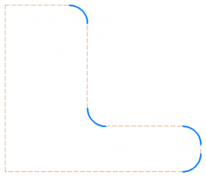
- 2D fillet – a fillet applied in a 2D space for objects such as lines and arcs.
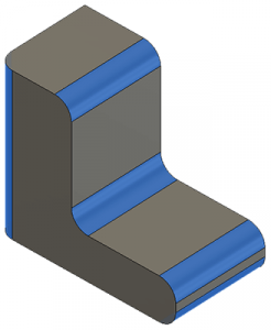
- 3D fillet – a fillet applied in a 3D space at the corners of solid objects.
Fillet based on corner type
Depending on the corner type of an object a fillet is generally categorised in AutoCAD into two categories:
- fillet – when it is added to an inside corner
- round – when it is added to an outside corner
Objects that can have a fillet applied
There are a large number of objects within AutoCAD that can have a fillet (or round) applied to them. These include 2D and 3D primitive objects. The full list of object in AutoCAD that can have a fillet applied to them is as follows:
- 2D polylines
- 3D solids and surfaces (not available in AutoCAD LT)
- Arcs
- Circles
- Ellipses and elliptical arcs
- Lines
- Rays
- Splines
- X-lines
AutoCAD – how to fillet 2D Elements
As mentioned above, a round or fillet can be created between two objects of the same or different object types: 2D polylines, arcs, circles, ellipses, elliptical arcs, lines, rays, splines, and x-lines.
If the two selected objects are on the same layer, the arc defined is created on that layer. Otherwise, the arc is created on the current layer. The layer affects object properties including color and linetype.
An abstract workflow of adding a fillet on two compatible objects is described below. Please note that there are different variations depending on the object types selected. There are also multiple options that can be applied to the fillet such as trim mode.
AutoCAD – How to Fillet – Abstract Example
In order to successfully apply a fillet in AutoCAD you must keep in mind the following:
- Objects must be of compatible types (listed above).
- Lines must not be parallel. If these are parallel your fillet command will not work.
- Depending on the object type you will have variation in the options. Make sure you apply these before selecting the second object.
Now, follow these steps in AutoCAD in order to apply a fillet:
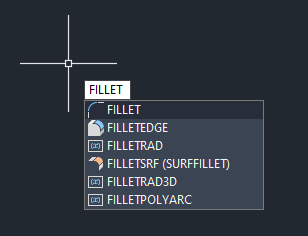
Step 1 – Run the FILLET Command
Select the Fillet option from the Modify tab group

or run the FILLET command.
Step 2 – Set the fillet radius
Right-Click anywhere in the Model Space and select Radius to define a radius for the fillet.
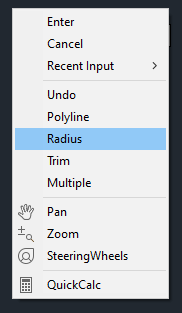
You can either enter the value of the radius in your desired units or define it as a distance on the screen.
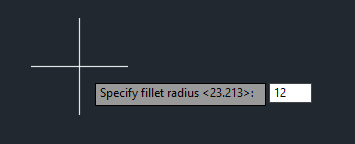
Alternatively, you can type in R in the command line to set the same value via commands.

Step 3 – Select the first object
Select the first of the object you want to fillet. This can be any of the compatible objects listed above.

Step 4 – Select the second object to apply
Select the second object to define the fillet to complete the command.

Step 5 – Results
Once finalised, the fillet will be applied between the two selected objects with the specified radius.

The two objects will be modified and trimmed if this option was selected (default).

